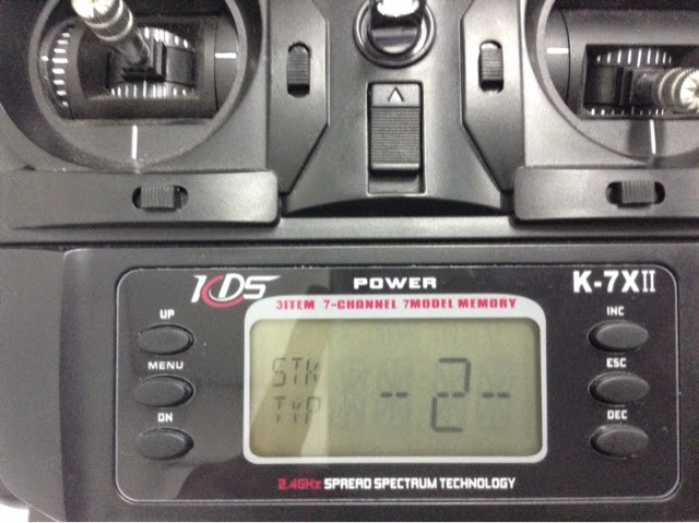
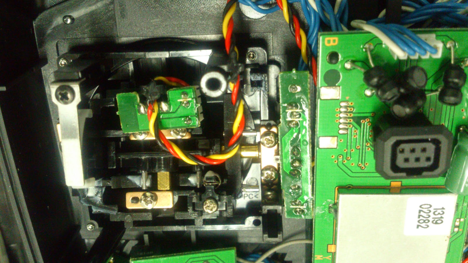
My Drone Hobby is the blog to sharing the ismi hobby on the DIY project of the remote controlled and electronics project. The project for drone started on the end of 2012.
Monday, June 30, 2014
Sunday, June 29, 2014
Saturday, June 28, 2014
Monday, June 9, 2014
Monday, June 2, 2014
My DIY Cloverleaf Antenna
Thursday, May 22, 2014
How Antenna Gain affects Range in FPV
http://blog.oscarliang.net/how-antenna-gain-affects-range/

To increase the range of the reception range of the radio system, there are two ways: either to increase the power of the transmitter or the power gain of the antenna.
As RC hobbyist we usually try to avoid modifying the transmitter to increase the power, or use a high power one, because that would add more weights to the plane. So that left us with the second option – increasing the gain of the antenna. However there are always misunderstanding about the concept of antenna gain.
To make it easier to understand, imagine we have a balloon and the amount of air in it is like the power of the system (the range) which is constant. The reason we are getting a larger range is because we are “pressing the balloon” and the shape of the balloon is changed (the increase of intensity of the radio signal toward certain direction). This way we sacrifice coverage of some direction to increase the range of other direction, but the total covered area is the same.

Although the range becomes narrower when increase the gain, we can put a multiple channel diversity controller to put more antenna in. This way we have more signal coverage and the system will pick the antenna that has the strongest signal to use.
A radiation pattern of the hypothetical isotropic antenna at 0db.

This is a standard omnidirectional 3 dB rubber duck antenna.

8dB Patch directional antenna

So when choosing antenna, unless you know what you are doing, you should choose a low dB omnidirectional antenna since the airplane is moving around in all directions, so you don’t lost connectivity when turning. Alternatively if using high db antenna, also use a diversity controller and add more antenna to cover more space. Check out my post about how polarization affects the performance of an antenna.
On the receiver side, you can consider using a patch antenna which allows you fly further in one direction, and you can turn it around to face your airplane to maximize the reception. If you plan on flying around yourself, a 3dBi omnidirectional or something similar would be safe.
How Antenna Gain affects Range in FPV
To increase the range of the reception range of the radio system, there are two ways: either to increase the power of the transmitter or the power gain of the antenna.
As RC hobbyist we usually try to avoid modifying the transmitter to increase the power, or use a high power one, because that would add more weights to the plane. So that left us with the second option – increasing the gain of the antenna. However there are always misunderstanding about the concept of antenna gain.
Understand Antenna Gain
The gain or loss of antenna is measured by decibel (dB), which is equal to 10*log(Pout/Pin). Every 3dB increase in the gain, it doubles the range of the Antenna. However, here is the thing, it does not really “double” the range but more like taking the range from other direction and focus on the desired direction.To make it easier to understand, imagine we have a balloon and the amount of air in it is like the power of the system (the range) which is constant. The reason we are getting a larger range is because we are “pressing the balloon” and the shape of the balloon is changed (the increase of intensity of the radio signal toward certain direction). This way we sacrifice coverage of some direction to increase the range of other direction, but the total covered area is the same.
Although the range becomes narrower when increase the gain, we can put a multiple channel diversity controller to put more antenna in. This way we have more signal coverage and the system will pick the antenna that has the strongest signal to use.
Radiation Pattern
That was a very rough description of the idea. The actual shape of the radio frequency signal coverage changes irregularly with the antenna gain.A radiation pattern of the hypothetical isotropic antenna at 0db.
This is a standard omnidirectional 3 dB rubber duck antenna.
8dB Patch directional antenna
Conclusion
By increasing Antennas Gain do not magically create extra power but simply focus the radiated radio frequency into narrower space, so the signal coverage can reach out further in the required direction. Remember that by gaining distance the effective angle will be lost.So when choosing antenna, unless you know what you are doing, you should choose a low dB omnidirectional antenna since the airplane is moving around in all directions, so you don’t lost connectivity when turning. Alternatively if using high db antenna, also use a diversity controller and add more antenna to cover more space. Check out my post about how polarization affects the performance of an antenna.
On the receiver side, you can consider using a patch antenna which allows you fly further in one direction, and you can turn it around to face your airplane to maximize the reception. If you plan on flying around yourself, a 3dBi omnidirectional or something similar would be safe.
Make a DIY Cloverleaf Antenna
http://blog.oscarliang.net/make-diy-cloverleaf-antenna/


It is not the ideal receiver antenna however, because the reverse polarization rejection pattern is very erratic. You need to choose other types of antennas for the receiver.
Also it’s not easy to make, pretty fragile, takes up space, affected by wind, and not possible to tune to the desired frequency after it’s made.


To make it easier for our readers, you can use this tool to calculate the required length of the wires.
Use this tool to calculate where to bend the wires.
As an example, for the most common 5.8 GHz FPV system (5800 Mhz), the length of the wires should be 52.93mm, and it should be bend at 13.2mm. This is what the shape and measurements should look like.

Measure and cut 3 pieces of the calculated length, cut them a bit longer (marked as optional above, so you have the extra length to solder to the main wire. Trim both ends so they are flat. Pretty straightforward, I followed this youtube video.


Solder the wires to the coax cable one by one about 120 degree apart.


And tilt the wires to the right 45 degree. This will make the antenna “right handed” polarized, since this is a more common configuration.


Now bend the wires, so the tip of the wires can reach the signal wire of the coax cable.


And finally solder all the tips together to the signal wire.


Virevent Antenna (4 lopes)

Windmill Antenna (5 lopes)


The key factor of making a successful FPV antenna is to be precise with measurement. The more accurate you can make the antenna the better it will perform.
Make a DIY Cloverleaf Antenna
What is a Cloverleaf Antenna
The cloverleaf antenna is a circular polarized antenna which is way better than the cheap whip antenna that comes with most transmitters. In fact it is one of the best FPV video transmitter antennas available to hobbyists at the moment. I explained the benefits of a circular polarized antenna over a linear one if you are not sure what are the differences. The Cloverleaf is a closed loop antenna which the signal and ground wires are connected. The cloverleaf antenna has 3 loops at 120 degree apart, and they are titled at 45 degree.Good and bad things about Cloverleaf Antenna
Circular polarized antennas are great for FPV video streams because they’re good at rejecting phase shifted signals (distorted signal). The cloverleaf antenna has an excellent radiation pattern and very low gain. It’s possible to achieve a 1.0 SWR which is the perfect efficiency in signal transmission.It is not the ideal receiver antenna however, because the reverse polarization rejection pattern is very erratic. You need to choose other types of antennas for the receiver.
Also it’s not easy to make, pretty fragile, takes up space, affected by wind, and not possible to tune to the desired frequency after it’s made.
Let’s get started!
Parts you will need
- 0.8mm copper clad welding wire, it’s stiff and easy to solder (some people used 0.6mm also worked fine)
- RG316 coax cable (or RG405)
- Soldering tool
Measuring and Cutting the antenna wires
The size of the antenna (the length of the wires) does not follow the rule of “the bigger the better”. The length of the antenna wires affects what signal frequency you can receive. The length you need for your desired frequency can be calculated using mathematical equations. Generally the length of wires would be smaller for higher frequency signals.To make it easier for our readers, you can use this tool to calculate the required length of the wires.
Use this tool to calculate where to bend the wires.
As an example, for the most common 5.8 GHz FPV system (5800 Mhz), the length of the wires should be 52.93mm, and it should be bend at 13.2mm. This is what the shape and measurements should look like.
Measure and cut 3 pieces of the calculated length, cut them a bit longer (marked as optional above, so you have the extra length to solder to the main wire. Trim both ends so they are flat. Pretty straightforward, I followed this youtube video.
The 3D design diagram with angles
Soldering
Cut your coax cable open like this, so the ground and signal wires are exposed and ready to be soldered.Solder the wires to the coax cable one by one about 120 degree apart.
And tilt the wires to the right 45 degree. This will make the antenna “right handed” polarized, since this is a more common configuration.
Now bend the wires, so the tip of the wires can reach the signal wire of the coax cable.
And finally solder all the tips together to the signal wire.
Other Polarized Antenna Design
Skew Planar Wheel Antenna (4 lopes)Virevent Antenna (4 lopes)
Windmill Antenna (5 lopes)
Conclusion
It’s been suggested that the circular polarized antenna at the transmitter side works better with a helical antenna at the receiver. But of course it’s your choice and the results vary from case to case.The key factor of making a successful FPV antenna is to be precise with measurement. The more accurate you can make the antenna the better it will perform.
Subscribe to:
Posts (Atom)